How to Manage Solar Facade Wiring Problems: The 2026 Technical Guide
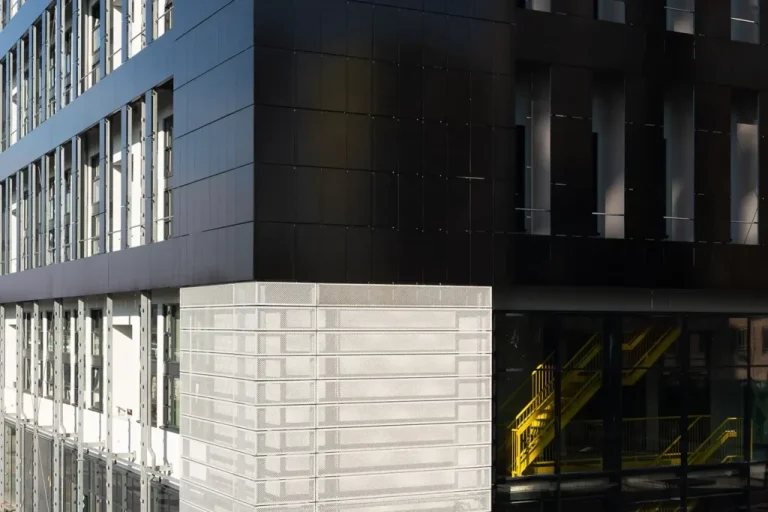
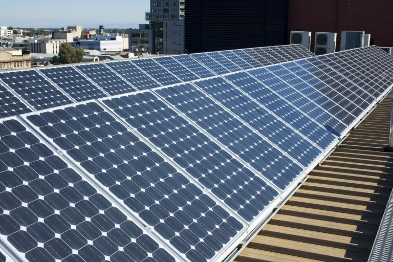
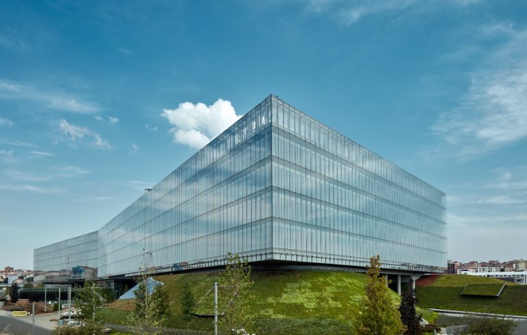
How to manage solar facade wiring problems in the architectural evolution of the 21st century, the transition from passive building envelopes to active energy generators is perhaps the most significant shift in material utility. Building-Integrated Photovoltaics (BIPV) have transformed the traditional facade into a vertical power plant, yet this integration brings a unique set of electrical challenges. Unlike rooftop solar, where wiring is often accessible and layout is secondary to the roof’s geometry, a solar facade must harmonize with the aesthetic, structural, and fire-safety requirements of the building’s skin.
The complexity of solar facade systems often leads to a “performance gap” where theoretical energy yields are undercut by systemic electrical inefficiencies. While mechanical and structural failures are visible to the naked eye, wiring malfunctions are insidious, manifesting as silent parasitic losses, localized thermal stresses, or, in extreme cases, arc-fault hazards. The difficulty is compounded by the fact that these systems are often “buried” within curtain walls or rainscreen cavities, making traditional troubleshooting and repair both physically and financially prohibitive.
As we progress through 2026, the industry is moving away from bespoke, artisan-wired facades toward standardized, modular electrical topologies. Effective asset management now requires a departure from the “solar-as-an-appliance” mindset toward “solar-as-infrastructure.” To manage these systems successfully, one must understand the interplay between DC voltage drop, galvanic isolation, and the metabolic thermal cycles of the building. This pillar article provides a definitive roadmap for engineers and facility managers on the technical rigor required to maintain electrical continuity in the modern vertical array.
Understanding “how to manage solar facade wiring problems”
How to manage solar facade wiring problems to master how to manage solar facade wiring problems, one must first recognize that a facade is a dynamic, moving environment. High-rise buildings sway, materials expand under the desert sun, and gaskets shrink in the winter. A common misunderstanding in BIPV is treating the wiring as a static circuit. In reality, the wiring is subject to constant mechanical stress. If the “loop slack” is insufficient or if the cable management system does not account for thermal expansion, the insulation will eventually chafe against the metal frame, leading to a ground fault that can shut down an entire section of the building’s power generation.
Oversimplification in the design phase often leads to “Systemic Inaccessibility.” Architects frequently prioritize the visual “seamlessness” of the facade, leading to wiring being tucked into structural members that are sealed with structural silicone. This makes it impossible to replace a failed bypass diode or a corroded connector without destroying the weather seal of the building. Managing these problems, therefore, begins at the design stage with the implementation of Serviceable Raceways—dedicated channels that allow for electrical maintenance without compromising the building’s thermal or moisture barriers.
Furthermore, many facility managers fail to differentiate between Leading and Lagging electrical signals. A drop in energy production (lagging) is often the first sign of a problem, but by the time it is noticed, the damage—such as an arc-fault or a scorched junction box—may already be irreversible. Effective management involves monitoring Insulation Resistance (Riso) as a leading indicator. A gradual decline in Riso values indicates moisture ingress or insulation degradation long before a total system failure occurs.
Deep Contextual Background: The Electrical Skin How To Manage Solar Facade Wiring Problems
Historically, BIPV was an afterthought of the glazing industry rather than a priority for the electrical industry. Early vertical solar projects in the United States often used standard MC4 connectors and PV wire designed for rooftop air-flow. When these components were trapped in the stagnant, high-heat air of a curtain wall spandrel, they reached temperatures exceeding $90^{\circ}C$. This led to “connector annealing,” where the plastic housing became brittle and the internal metal contacts oxidized, creating high-resistance “hot spots.”
By 2026, the maturation of the BIPV market has led to the adoption of the NEC 690.12 Rapid Shutdown requirements for facades, fundamentally changing how we wire buildings. We have moved from long high-voltage DC strings to Module-Level Power Electronics (MLPE). This shift has solved many shading problems but has introduced a new maintenance variable: hundreds of individual micro-inverters or optimizers hidden behind the glass. The management of these systems is now as much a data-science challenge as it is a mechanical one.
Conceptual Frameworks and Mental Models
1. The “Cell-to-Grid” Continuity Model How To Manage Solar Facade Wiring Problems
This framework views the electrical path as a single chain with discrete “Vulnerability Points.” In a facade, the weakest link is typically the transition point where the module’s pigtail wire enters the building’s interior. Management must focus on the protection of these transition points from both ultraviolet (UV) degradation and mechanical shearing.
2. The “Thermal Siphon” Theory
Wiring performance is inversely proportional to temperature. This model suggests that wiring should always be located in the “coolest” part of the facade cavity—typically the lower intake area of a ventilated rainscreen. To manage wiring problems, one must manage the airflow around the cables to prevent the “Ohmic Heating Loop,” where resistance creates heat, which in turn creates more resistance.
3. The “Sacrificial Connector” Strategy
A mental model for maintenance planning. It assumes that connectors in a high-UV, high-moisture environment have a finite life of 15 years. Budgeting for a “connector refresh” at the mid-life point of the asset is more cost-effective than dealing with sporadic, emergency failures that require specialized high-access equipment like swing stages or industrial rope access.
Key Categories: Taxonomy of Wiring Failures
Successful management requires a precise classification of electrical risks.
| Failure Category | Primary Driver | Physical Symptom | Mitigation |
| Ground Faults | Insulation chafing; moisture | Riso alert; inverter trip | Low-smoke zero-halogen (LSZH) cabling |
| Arc Faults | Loose connectors; corrosion | Localized scorching; fire risk | AFCI-equipped inverters |
| Thermal Derating | Stagnant air in cavity | Voltage drop; low efficiency | Ventilated wiring raceways |
| Galvanic Corrosion | Dissimilar metal contact | Connector pitting; high resistance | Dielectric grease; compatible metals |
| EMI Interference | Poor shielding near HVAC | Data loss; monitoring errors | Twisted-pair shielded comms cables |
| Rodent Damage | Nesting in rainscreens | Open circuits; chewed insulation | Stainless steel braided sleeving |
Decision Logic: Micro-inverters vs. String Optimizers How To Manage Solar Facade Wiring Problems
In high-rise scenarios, the decision often comes down to Maintenance Access. If the building has an external window-washing track, micro-inverters (located on the exterior) are manageable. If the building is a “sealed box,” string optimizers located in internal electrical closets are the superior choice for budget-conscious maintenance, as they remove the electrical complexity from the inaccessible “hot zone” of the facade.
Detailed Real-World Scenarios
1. The “Expansion Joint” Shear
A mid-rise residential project in Denver used large-format BIPV glass.
-
The Problem: The wiring was zip-tied tightly to the aluminum frame across a structural expansion joint.
-
The Failure: During a record-breaking cold snap, the building’s contraction pulled the wiring taut, snapping the internal copper conductors inside the insulation. The system showed “Open Circuit” but the break was invisible.
-
The Solution: Retrofitting with “Service Loops”—extra 6-inch coils of wire at every structural junction to allow for movement.
2. The “Spandrel Oven” Effect
A sleek glass office tower in Phoenix utilized opaque BIPV in the spandrel zones.
-
The Problem: The wiring was bundled in the unventilated space behind the glass.
-
The Failure: Ambient temperatures in the cavity hit $105^{\circ}C$. The standard PVC insulation on the cables began to off-gas and soften, leading to a massive “short-to-frame” event.
-
The Solution: Replacing the bundle with Teflon-coated (PTFE) high-temperature wiring and introducing convective vents at the top and bottom of the spandrel glass.
Planning, Cost, and Resource Dynamics How To Manage Solar Facade Wiring Problems
The “Soft Costs” of wiring management in BIPV can outweigh the hardware.
| Resource | Unit Cost (2026 Est.) | Impact on Risk |
| I-V Curve Tracing | $2.50 / sq ft | High (Identifies hidden degradation) |
| IR Drone Inspection | $1,500 – $3,000 / day | Moderate (Finds hot spots) |
| High-Access Crew | $4,000 / day | Critical (The cost of fixing a $5 connector) |
| DC Optimizers (MLPE) | $15 – $25 / module | High (Isolates wiring faults) |
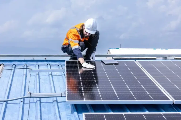
The Cost of “Hidden” Wiring: A common fiscal mistake is failing to account for the interconnection labor. Wiring a vertical facade takes 3x longer than a roof because every connection must be made while suspended or from a lift, and every wire must be meticulously “dressed” to prevent shadows on the cells below.
Tools, Strategies, and Support Systems
-
Electroluminescence (EL) Imaging: This tool allows technicians to “see” the current flow through the cells. A wiring problem often shows up as a “dark cell” or a “shunted string” that is invisible to the naked eye.
-
Smart Junction Boxes: 2026-era junction boxes now include integrated temperature sensors that can alert the Building Management System (BMS) before a connector reaches the melting point.
-
TDR (Time Domain Reflectometry): Essential for facades. A TDR meter sends a pulse down a wire to find the exact foot-marker where a break or short has occurred behind the glass.
-
Dielectric Silicone Grease: A simple but vital strategy for coastal BIPV. Filling connectors with dielectric grease prevents salt-air from initiating the corrosion cycle.
-
Stainless Steel Mesh Sleeving: In urban environments, squirrels and pigeons are a primary cause of wiring faults. Protecting “pigtails” with metal mesh is a high-ROI strategy.
-
Digital Twin Monitoring: Software that compares the real-time voltage of Panel A to Panel B. If Panel A is 5% lower than its neighbor under identical light, the system flags a “Connection Resistance” event.
Risk Landscape: The Cascade of Failure
Wiring problems in BIPV are rarely solitary. They follow a Compounding Taxonomy:
-
Phase 1: Resistance. A connector loosens due to vibration.
-
Phase 2: Thermal Stress. The loose connection creates a “Hot Spot.”
-
Phase 3: Material Fatigue. The heat causes the surrounding glass to expand unevenly, leading to a micro-crack in the solar cell.
-
Phase 4: Arc-Fault. The micro-crack creates a localized arc, which eventually melts the junction box and trips the building’s fire suppression alerts.
Governance and Long-Term Adaptation How To Manage Solar Facade Wiring Problems
To manage these systems over a 25-year lifespan, the property owner must implement a Metabolic Audit Schedule:
-
Quarterly: Review BMS logs for “Ground Fault Interrupt” (GFI) warnings.
-
Annually: Infrared (IR) scan of the facade during peak sun to find thermal anomalies in the wiring.
-
Every 5 Years: Detailed insulation resistance testing (Megger testing) of all home-run cables.
The Transition Trigger: When a facade section drops below 80% of its “Expected-to-Actual” yield for more than two consecutive quarters, a physical inspection of the connectors is mandatory. Ignoring this trigger is how a simple wiring issue turns into a full-scale facade replacement.
Common Misconceptions and Industry Myths
-
Myth: “Standard PV wire is fine for facades.” Correction: Facades require specialized fire-rated, low-smoke (LSZH) cabling to meet interior building codes, as the wiring is often technically “inside” the wall assembly.
-
Myth: “If the inverter is on, the wiring is fine.” Correction: High-resistance connections can steal 10% of your energy without ever tripping a breaker.
-
Myth: “Wireless monitoring eliminates wiring problems.” Correction: Wireless monitoring only reports the problem; the physical wiring remains the primary point of failure.
-
Myth: “Zip-ties are a permanent solution.” Correction: Standard plastic zip-ties fail in 3-5 years under UV stress. Only stainless steel or UV-stabilized clips should be used in BIPV.
Conclusion
The successful management of solar facade wiring is the difference between a high-performing architectural asset and an expensive, glass-clad liability. In the 2026 landscape, we no longer have the luxury of “install and forget.” The complexity of the vertical power plant demands a disciplined approach to electrical hygiene—prioritizing accessibility, thermal management, and proactive monitoring. By moving away from buried, inaccessible wiring and toward modular, serviceable systems, we ensure that the building’s skin remains as productive on Day 10,000 as it was on Day 1. The integrity of the energy transition depends not just on the efficiency of the cell, but on the resilience of the wire that carries its promise.